How to Develop Robust Motion Detectors for Smart Home & Building Applications
Protection, control, and sensing considerations for a simpler, more resilient design
By Ryan Sheahen, Littelfuse
Today’s smart buildings—from residential homes to commercial structures—are benefitting from intelligent technologies that enable them to be more convenient, safer, and energy-efficient. The wide range of products available for smart building applications is shown in Figure 1. Both home consumers and building management personnel can automatically monitor and control these devices remotely, even when not on-site.
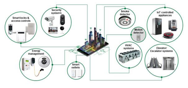
Figure 1. Intelligent devices that enable security, convenience, safety, and efficient energy management in homes and buildings
Infrared motion detectors are one product that combines convenience, safety, and energy conservation. An infrared motion detector senses an area is occupied and then activates lighting, the HVAC system, or an alarm. If the motion detector also incorporates security functionality, it needs to operate reliably 24 hours/7 days a week without downtime.
The leading technology for motion sensing is passive infrared (PIR) due to the combination of reliable performance and low cost. Factors driving the market’s healthy compound annual growth rate, which is over 13% and will likely exceed $3.5 B in 20251, include
- Residential demand for security using surveillance
- Reducing cost of installation with wireless connectivity and IoT networks
- Governmental energy conservation initiatives that are being adopted in public and commercial sectors.
This article addresses concepts that ensure your design will be robust to external disturbances. In addition, it presents an infrared detector assembly that significantly reduces your design’s parts count while improving product performance and reliability.
Protection, control, and sensing components
for passive infrared motion detectors
Since PIR motion detectors may be used for either interior or outdoor monitoring, these products must be robust to environmental disturbances. If the detectors are powered by the AC line, they need to withstand current overloads and voltage transients that can propagate on the AC power line. In addition to robust circuit protection, efficient control and reliable sensing performance are essential for a quality end product. An example infrared motion detector (see Figure 2) defines several recommended protection, control, and sensing components that enhance both product reliability and performance.
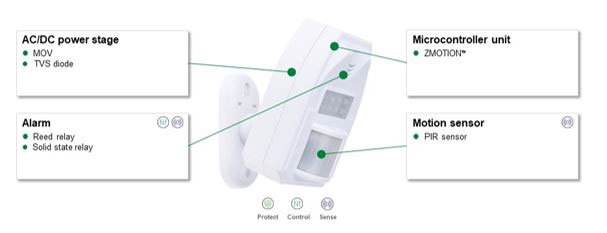
Figure 2. An example PIR motion detector showing recommended protection, control, and sensing components
The block diagram (see Figure 3) shows a PIR motion detector, identifying in which circuits the recommended protection, sensing, and control components should be placed. The following sections discuss each block in which components are recommended.

Figure 3. Block diagram of a PIR motion detector showing the circuits where the recommended components are located
AC/DC Power Stage
The AC/DC Power Stage provides the DC power for the other circuits. Because this circuit interfaces with the AC power line, it is subject to overcurrent surges and overvoltage transients. Overvoltage transients and current surges can result from lightning strikes, inductive spikes from motor turn-on and turn-off, and transients from power line voltage variations. Against these potential disturbances, a metal oxide varistor (MOV) is recommended as the first line of defense for the AC/DC power stage board. Locate the MOV as close as possible to the entrance of the AC voltage on the circuit to minimize the propagation path for AC line transients on the circuit board. Select an MOV with these characteristics:
- Safe absorption of up to 10 kA peak surge current or 150 J of pulse energy to protect downstream circuitry from a lightning strike
- Low clamping voltage that will not damage downstream circuitry
- An operating temperature range to ensure the component will function over the detector’s specified environmental range (versions of MOVs with phenolic coating can operate safely up to 125 °C)
- Reduce qualification time by selecting components certified by UL- or IEC-recognized standards labs.
At the output of the AC/DC Power Stage, consider using a transient suppressor (TVS) diode for further protection of all the load circuits on the power supply. The TVS diode will minimize transient stress on the power components in the various load circuits. The TVS diode offers these benefits for circuit protection:
- Absorbance of as much as 600 W of peak pulse power or 100 A of peak surge current
- ESD protection that can be as high as 30 kV either from through-the-air strikes or direct contact
- Ultra-fast response, under 1 ps, to a transient
- Versions that have clamping voltages as low as 10 V
- UL or IEC component recognition
TVS diodes can be bi-directional, using two series diodes in a package, or uni-directional, with a single diode (Figure 4). In addition to their protection features, TVS diodes consume a small amount of power. In normal, disturbance-free operation, the component draws under 1 µA. Finally, surface mount versions of TVS diodes are available for conserving printed circuit board (PCB) real estate.

Figure 4. Bi-directional and Uni-directional TVS diodes for protection from ESD and other electrical transients
Motion Sensor and MCU
The main elements of the PIR detector are the infrared radiation sensor and the microcontroller unit. Be aware that complete packages are available that include a sensor, a lens, and a microcontroller unit (see Figure 5). A complete package offers:
- Reduction of the design’s bill of material since the sensor connects directly to the microcontroller chip.
- A microcontroller that contains all the circuitry needed for a complete design for the detection and processing electronics. The microcontroller contains the CPU, RAM, timers, comparators, A/D converter, communication interface, and the firmware for the sensor.
- 2-element or a 4-element sensor that, combined with a lens, can offer numerous options for different fields of vision.
- Designs that allow the use of lower cost and smaller ceramic capacitors compared with typical usage of electrolytic capacitors which have higher leakage and a shorter product life
- Advanced motion detector algorithms that provide sensitivity, range, and field of detection management
- Flexibility in the microcontroller to allow implementation of user-defined application features.

Figure 5. Block diagram of a combination lens, sensor, and microcontroller assembly
To save power during long periods of inactivity, look for an assembly that incorporates a low power mode when no motion is detected. Figure 6 shows an example infrared motion detector package. The combination of an integrated package with fewer components and no electrolytic capacitors improves overall product reliability, saves PCB space, and reduces cost.

Figure 6. An example lens-sensor-microcontroller infrared motion detector assembly. This assembly is from Zilog. The lens and sensor are on top of the PCB. The microcontroller is underneath the sensor.
Alarm
The alarm circuit activates when the infrared sensor detects an appropriate amount of motion. Typically, the circuit drives a flashing LED light or an LED light and speaker combination. The alarm circuit needs a control component to energize the external device. Consider either a solid-state relay or reed relay, both of which will provide galvanic isolation of the high-power drive from the low power logic circuitry. A solid-state relay offers longer life for the output drive contacts, while a reed relay offers lower power consumption.
Reed relays are available in compact single-in-line packages. You can also get reed relays with built-in back EMF suppressor diodes to protect the coil drive circuit and with magnetic shield options to prevent the coil EMI from entering the control circuitry. In addition, reed relay contacts have a longer life than conventional electromechanical relays, and they are relatively immune to wide ranges of environmental temperatures.
Solid-state relays optically couple control between an input LED and an output photodetector transistor. Solid-state relays can have as much as 1500 Vrms isolation between input and output. Many are designed to eliminate EMI/RF generation with logic that initiates switching at zero voltage crossings. Versions of solid-state relays can have a low off-state output leakage current of under 1 µA to minimize power consumption. They are available in space-saving, surface-mount packages.
Your choice of drive component will depend on ensuring the contacts or the output have sufficient drive capacity for the types of outputs that will be used. Size, power consumption, and cost will be other factors that you will want to factor in your choice of drive component.
Safety Standards for PIR Motion Detectors
Table 1 lists critical standards that your design needs to conform to so that it can be certified and obtain market acceptance. Adhering to these standards as part of the development process will reduce certification costs as well as certification time. Complying with the IEC standards will permit sales of your product in all worldwide regions.

Table 1. Standards that govern safety and minimum operational requirements for PIR motion detectors
Summary
Robust, reliable designs can have a low component count and low development costs.
Bottom line: For an infrared detector design, a robust design requires only a few protection components. You can take advantage of a lens/sensor/microcontroller package to reduce parts count and maximize product reliability. Be sure to include standards compliance as an important element of the development project to save certification time and costs.
When available, it is wise to take advantage of a manufacturer’s applications expertise to help save time when selecting the necessary protection and control components, which can also help save significant design time. The manufacturer can also provide guidance on which standards apply to the design and how to ensure compliance. These recommendations will help you achieve a robust, reliable design that will result in fewer field failures and a more cost-effective and profitable product.
References
Occupancy Sensor Market. Markets and Markets. July 2020.
Additional Reference Literature available at Littelfuse.com:
- Circuit Protection Selection Guide
- Sensing Products Selection Guide
- Power Semiconductor Selection Guide
- Zilog ZMOTION™ Detection Module Datasheet
Smart Motion Detection Circuit Protection Solutions
The HE3300 miniature reed relay in a Single-In-Line (SIL) package provides a choice of normally open, normally open high voltage, or changeover contacts. Capable of switching up to 300 Vdc at 10 W. Benefits include:
- Single-in-line configuration allows high packing densities, minimizing space and cost
- Lower coil power consumption than electromechanical devices
- Hermetically sealed switching contacts are immune to their environment
- Transfer molded package gives maximum component protection
Miniature single-pole, normally-open (1-Form-A) The CPC1017N solid state relay in a 4-pin SOP package. Employs optically coupled MOSFET technology to provide 1500 Vrms of input to output isolation. This SSR features:
- Designed for Use in Security Systems Complying with EN50130-4
- Only 1mA of LED Current Required to Operate
- Arc-Free with No Snubbing Circuits
- No EMI/RFI Generation
- Immune to Radiated EM Fields
The LV UltraMOV Varistor Series of low voltage, high surge current, radial leaded varistors provides an ideal circuit protection solution for lower DC voltage applications by offering higher surge ratings than ever before available in such small discs.
- 5 model sizes available: 5, 7, 10, 14, and 20mm
- High peak surge current rating up to 10kA (8/20 μs pulse)
- Wide operating voltage range VM(AC)RMS 11V to 95V and V M(DC) 14V to 125V
- High operating temperature range up to 125ºC
SMBJ 600W Surface Mount TVS Diodes
The SMBJ TVS Diode Series is available in a low-profile, surface-mounted package to optimize PC board space. These TVS diodes are designed to protect sensitive equipment against ESD according to IEC 61000-4-2 and electrical over stress according to IEC 61000-4-4 and 5.
- Excellent clamping capability
- Low incremental surge resistance
- Typical IR less than 1µA above 12V
- Typical failure mode is short from over-specified voltage or current

