For the better part of three decades, the data center has been powered in much the same way. Utility power arrives as alternating current; passes through transformers, switchgear and uninterruptible power supplies; and is converted again and again before it reaches the server. It is then stepped down to the 54-volt, 12-volt and sub-one-volt rails used by the AI microprocessors. Every one of those points of demarcation carries its own bill of materials for capacitors and very stable electrostatic and electrolytic ecosystems around that architecture.
In 2026, that electrical/electronic architecture model began to demonstrate signs of strain. The power drawn by a single AI rack rose from tens of kilowatts to well over 100 kilowatts, with the trend continuing, and the industry is now planning for racks of above one megawatt. At those power levels, low-voltage distribution inside the rack is no longer efficient or practical. The current answer that the AI hyperscale ecosystem has settled on is 800-volt direct current (800 VDC), and the decision has significant consequences for capacitor technologies and their respective raw material supply chains.
This article examines the 800 VDC transition from the standpoint of the capacitor supply chain: where capacitors sit in the new power chain, which dielectrics benefit, which are displaced and what it means for the global market through 2031.
Defining the 800-Volt Transition
NVIDIA set the direction in May 2025 when it announced that it would support one-megawatt IT racks starting in 2027, and that full-scale production of 800 VDC data centers would coincide with its Kyber rack-scale systems that year. More than a dozen semiconductor companies, power system suppliers and data center infrastructure vendors were named as partners, including Infineon, Texas Instruments, STMicroelectronics, onsemi, ROHM, Navitas, Delta, LiteOn, Eaton, Schneider Electric and Vertiv. Capacitor manufacturers should be viewing these customers as key growth partners for fiscal year 2027 through 2031.
The program has moved quickly. In March 2026, NVIDIA, Google and Microsoft published an 800 VDC white paper through the Open Compute Project, and in July 2026, the group released version 0.3 of a low-voltage DC solid-state transformer specification. In August 2026, NVIDIA said its first MGX-compatible 800 VDC power rack would arrive in the second half of 2026, that row power centers delivering up to two megawatts per rack row would follow in 2027 and that more than 80 equipment and infrastructure companies were building to the specification. Texas Instruments, for its part, introduced a complete 800-volt reference architecture in March 2026, running from hot-swap protection at the rack input down to the multiphase converters that feed the GPU core.
The engineering logic is simple. At a fixed power level, current falls as voltage rises. A one-megawatt rack fed at 54 volts would require roughly 18,500 amperes. At 800 volts, it requires about 1,250 amperes. NVIDIA estimates that 800 VDC reduces copper requirements by 45% compared with 415-volt AC distribution, carries 85% more power through the same conductor size, improves end-to-end efficiency by up to 5% compared with today's 54-volt systems and lowers maintenance costs by up to 70% – a remarkable achievement.
The important point is that 800 VDC does not remove capacitors from the data center. It relocates them, and it changes the voltage, temperature, frequency and energy-storage requirements they must meet.
Where Capacitors Sit in the 800-Volt Power Chain
Figure 1 traces the new power chain from the facility to the processor and identifies the capacitor content at each stage. I divided the chain into five stages.
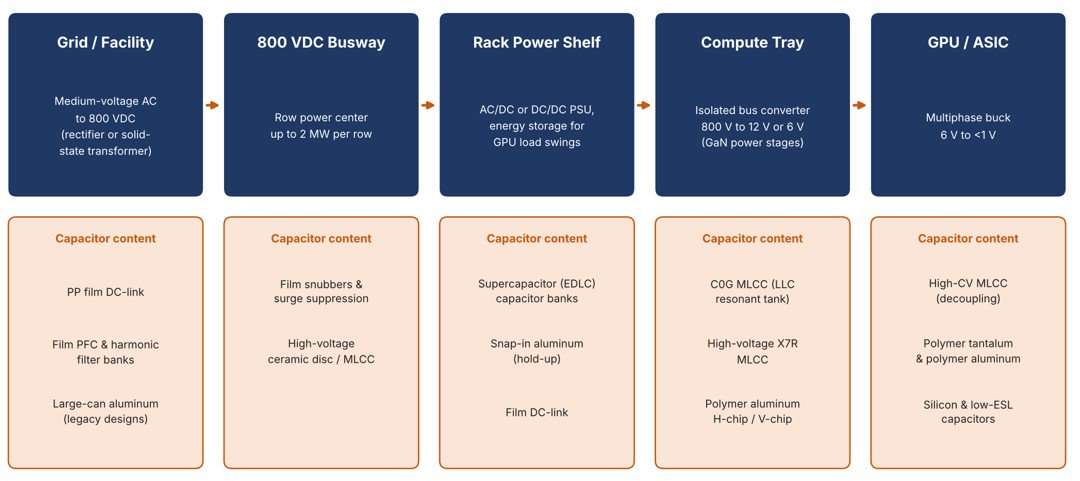
Figure 1: Capacitor Content by Stage in the 800 VDC AI Data Center Power Chain
Source: Paumanok Publications, Inc. analysis based on Aluminum Electrolytic Capacitors: World Markets, Technologies & Forecasts 2026–2031 (October 2026). www.paumanokgroup.com
Grid and facility. Medium-voltage AC is converted to 800 VDC by a rectifier or, increasingly, a solid-state transformer built on silicon carbide. This stage uses polypropylene film DC-link capacitors and film capacitor banks for power-factor correction and harmonic filtering.
The 800 VDC Busway. Power is distributed overhead to the rack row. Capacitor content here is modest but technically demanding: polypropylene film snubbers, polypropylene surge suppression and high-voltage ceramic chip and through-hole capacitors.
The Rack Power Shelf. Power supplies and energy storage modules sit here. This is where the new demand for carbon supercapacitor banks appears, alongside polypropylene film DC-link and aluminum electrolytic snap-mount hold-up capacitors.
The Compute Tray. An isolated bus converter steps 800 volts down to 12 or 6 volts, increasingly with gallium nitride power stages. These converters depend on C0G ceramic capacitors in the resonant tank, high-voltage X7R MLCCs and conductive polymer aluminum electrolytic chips.
The GPU and ASIC. Multiphase buck converters deliver less than one volt to the processor core. This remains the domain of high-capacitance base metal electrode (nickel) MLCCs, conductive polymer tantalum and conductive polymer aluminum capacitors and, increasingly, silicon capacitors (See Paumanok’s study on silicon capacitors).
Polypropylene Plastic Film Capacitors: The DC-Link Winner
The single largest beneficiary of the 800-volt transition is the metallized polypropylene film capacitor. Polypropylene film is self-healing, has very low dielectric losses, handles high ripple current and is available in voltage ratings well above 800 volts in a single winding. Those are exactly the characteristics needed for the DC-link, the bulk capacitor that sits between the rectifier and the downstream converter, absorbs transient energy and keeps the bus voltage stable. (See Paumanok’s study on plastic film capacitors).
Plastic dielectric film capacitors appear at every high-voltage stage of the new chain: at the output of the facility rectifier or solid-state transformer, inside the rack power shelf, in the snubbers and surge suppression modules on the busway and in the large power-factor correction and harmonic filter banks that serve the AI campus as a whole. The switch to silicon carbide and gallium nitride switching increases ripple current density in the DC-link, which further favors plastic film dielectric. Plastic film dielectrics, with emphasis upon polypropylene, have more than 100 years of use as an electrical capacitor at high voltage.
The technical challenge is heat. Standard polypropylene film capacitors are typically rated to 85°C with a maximum of 105°C, while industry commentary suggests that power stages in AI busways and racks can reach 125°C to 135°C. That gap is driving demand for higher-temperature film dielectrics and is a clear opportunity for vendors that can qualify them. It also raises a supply chain question that I have raised before for the electric vehicle and renewable energy markets: capacitor-grade polypropylene resin and the ultra-thin biaxially oriented film made from it come from a small number of producers.
AI data centers now compete for the same capacity as EV inverters, solar inverters, wind turbines and HVDC transmission – an important emerging market for dielectric plastic films which have provenance and utility in the high-voltage electrical ecosystem for power factor correction and harmonic filtering.
Aluminum Electrolytic Capacitors: Displaced at the Bus, Expanding at the Board
The 800-volt transition is more complicated for aluminum electrolytic capacitors. A single liquid electrolyte aluminum capacitor is practical up to roughly 450 to 550 volts. Meeting an 800-volt bus requires stacking capacitors in series with balancing resistors, which adds cost, board area and failure points. For that reason, plastic dielectric film is likely to take the DC-link position at 800 volts that large-can and snap-in aluminum capacitors have traditionally held in industrial drives and UPS systems.
That is only half the story. Snap-mount and large-can aluminum electrolytic capacitors remain essential for hold-up and bulk capacitance wherever intermediate bus voltages fall within their ratings, and in the very large installed base of AC-fed AI racks that will continue to be built and serviced for years. On the low-voltage side of the bus converter, the 800-volt architecture increases the number and value of conductive polymer aluminum electrolytic capacitors (H-chip, V-chip and some radial designs) on the compute tray and the accelerator board.
Ceramic Capacitors: Higher Voltage and Higher Frequency
The isolated bus converter is where multilayer ceramic capacitors gain the most. Texas Instruments' 800-volt to 6-volt bus converter, built with integrated gallium nitride power stages, reaches a peak efficiency of 97.6% and a power density above 2,000 watts per cubic inch. Converters of that density run at high switching frequencies, and their resonant tanks require C0G (NP0 – negative-positive-zero) ceramic capacitors, which hold their capacitance across temperature and voltage and have very low losses.
The same converters need high-voltage X7R MLCCs for input filtering and snubbing at 800 volts, often in stacked or large case sizes. These are not commodity parts. The vendor base for high-voltage, high-reliability MLCCs is far narrower than for the general-purpose chips and has internal chemistries based upon palladium and silver conductive metals. At the processor itself, the 6-volt to sub-one-volt conversion stage keeps the enormous count of high-capacitance BME (nickel) decoupling MLCCs that have defined AI server boards since 2023.
Carbon Supercapacitors: Energy Storage Returns to the Rack
One of the least appreciated features of the 800-volt architecture is that it brings energy storage directly into the rack. AI training workloads cause GPU power draw to swing sharply in fractions of a second, and those swings travel back up the power chain to the utility. NVIDIA has made energy storage part of the 800 VDC architecture specifically to absorb load spikes and sub-second power swings.
Electric double-layer capacitors (EDLCs), also called supercapacitors or ultracapacitors, are well suited to this job because they can deliver and absorb power very quickly over hundreds of thousands of cycles. Texas Instruments' reference architecture includes 800-volt capacitor bank units built from EDLC cells, with a power density of 40 watts per cubic inch. The fuel cell and on-site generation community is also looking at supercapacitors as a fast buffer on the DC bus.
For the supercapacitor industry, which has long depended on niche markets such as wind turbine actuation, electric transport boost power and CMOS memory hold-up, the AI rack could become its first truly high-volume application. That would also put new demand on the materials behind EDLC cells, particularly high-purity activated carbon electrodes and organic electrolytes. This application is also being addressed by conductive polymer tantalum capacitors, which work well in high heat environments.
Tantalum and Aluminum Electrolytic
Polymer tantalum capacitors retain their role at the point of load, alongside polymer aluminum chips, where low ESR, volumetric efficiency and a benign failure mode matter. The 800-volt transition does not change that position. If anything, the higher power per rack increases the number of point-of-load converters and the number of tantalum or aluminum electrolytic capacitance they require.
Figure 2 summarizes Paumanok's view of how the 800-volt transition affects each component family.
| Component | Role in 800 VDC Architecture | Paumanok Outlook |
|---|---|---|
| Polypropylene Film Capacitors | DC-link, snubbers, PFC and harmonic filter banks | Strong gain, high-temperature film is the key opportunity |
| Aluminum Electrolytic (Snap-In, Large Can) | Hold-up and bulk capacitance, legacy DC-link | Mixed, displaced at 800 V DC-link and supported by installed AC base |
| Polymer Aluminum (H-Chip and V-Chip) | Compute tray and accelerator board | Strong gain, ~10% annual growth for H-chips to 2031 |
| High-Voltage and C0G MLCCs | Resonant tanks, input filters and snubbers | Strong gain, narrow vendor base supports pricing |
| High-CV MLCCs | GPU and ASIC decoupling | Steady gain with rack power |
| Supercapacitors (EDLC) | Rack energy storage for GPU load swings | New high-volume market |
| Polymer Tantalum | Point-of-load conversion | Steady |
| Resistors | Balancing, precharge and current sense | Gain in high-voltage types |
| Inductors and Transformers | Bus converters, facility conversion | Shift to planar and high-frequency ferrite |
Figure 2: Impact of the 800 VDC Transition by Passive Component Family
Source: Paumanok Publications, Inc. analysis, based on 1) Aluminum Electrolytic Capacitors: World Markets, Technologies & Forecasts 2026–2031 (October 2026), 2) Plastic Film Capacitors: World Markets, Technologies & Opportunities: 2023-2028 - Deep Dive Analysis- ISBN# 0-929717-87-2 (2023), 3) Tantalum Capacitors: World Markets, Technologies and Opportunities: 2023-2027 - Deep Dive Analysis - ISBN #:1-893211-11-8 (2023) and 4) Silicon Capacitors World Markets, Technologies & Opportunities 2026 – 2031 ISBN # 1-893211-90-8 (SI2026) www.paumanokgroup.com
The materials picture follows from the table. The 800-volt data center pulls demand toward polypropylene resin and film, toward high-voltage etched and formed aluminum anode foil, toward activated carbon for supercapacitors and toward the nickel, silver and palladium used in high-voltage ceramic capacitors. I have written in this column about termination metal volatility and platinum group metal vulnerabilities in ceramic chip manufacturing and how the AI power build-out adds another source of demand to markets that are already challenged and under scrutiny.
I expect polypropylene film capacitors in large can, interference suppression and snubber capacitor designs; snap-mount and large can aluminum electrolytic capacitors for DC-link applications; high-voltage MLCCs in COG/NPO dielectric with palladium-silver electrodes; high capacitance BME (nickel) MLCCs for decoupling; solid polymer tantalum capacitors; and carbon supercapacitor markets to capture a larger share of new power-conversion content as 800 VDC designs move into volume production.
Summary
- 800-volt DC distribution is becoming the standard for AI racks of one megawatt and beyond, with first products in late 2026 and volume deployment beginning in 2027.
- The new architecture does not remove capacitors from the data center. It relocates them to higher-voltage, higher-temperature, higher-frequency and energy-storage roles.
- Polypropylene film capacitors are the clearest winner at the DC-link, but high-temperature performance and the concentrated supply of capacitor-grade film are the constraints to watch.
- Aluminum electrolytic capacitors lose the 800-volt DC-link position but gain polymer chip content on the compute tray and accelerator board, where lead times of 28 to 31 weeks show how tight supply already is.
- High-voltage and C0G ceramic capacitors, supercapacitors and high-voltage resistors are new growth markets created by the transition.
For component manufacturers, materials suppliers and investors, the 800-volt AI factory is a reason to look again at capacity plans for film, high-voltage ceramics, aluminum, tantalum and carbon EDLC cells.
Dennis M. Zogbi is Chief Executive Officer and Founder of Paumanok Publications, Inc., and a longtime contributing analyst to MarketEYE.
Statements of fact and opinions expressed in posts by contributors are the responsibility of the authors alone and do not imply the opinion of the officers or the representatives of TTI, Inc. or the TTI Family of Specialists.
Follow TTI, Inc. on LinkedIn for more news and market insights.
Statements of fact and opinions expressed in posts by contributors are the responsibility of the authors alone and do not imply an opinion of the officers or the representatives of TTI, Inc. or the TTI Family of Specialists.
Follow TTI, Inc. - Europe on LinkedIn for more news and market insights.
Statements of fact and opinions expressed in posts by contributors are the responsibility of the authors alone and do not imply an opinion of the officers or the representatives of TTI, Inc. or the TTI Family of Specialists.