Passive Components & Small Satellite Systems
Passive Component Technologies Applicable to Emerging Small Satellite Systems
7/15/2019 // R. Demcko, R. Edily, J. Marshall, J. Prieur
Abstract:
The growth in the number of satellites launches as well as the emergence of completely new classes of small satellites would have been difficult to predict a few decades ago. Even the magnitude of performance advances within larger satellites would have been difficult to envision.
The fact is that advances in flight systems is on track to continue this rate of change and along with that system trend comes a demand for advanced passive and active components which will be used to build ever smaller, lighter, more reliable end electronics.
This paper provides a high-level view at the emergence of ceramic capacitor technologies that will be utilized to enable future advanced system level designs. In light of all these changes, key pre-production conversations with an authorized distributor can ensure component availability when the project passes the final design gate and prevent the possibility of counterfeit components entering the supply chain.
Introduction – Competition, Innovation, Growth & Change:
Competition between various nations has been a given ever since the space age began. However, competition from public & private entities within a particular country is something that is relatively new. The intensity of this competition if fueled by true innovation ranging from new material systems and manufacturing methods to complex modeling capabilities.
Completely new concepts of Nano & Microsats are being embraced along with acceptance of constellation-based networks of these simple but powerful spacecraft. Semiconductor advanced have proven critical to the nanosat/microsat sector. The main trends of semiconductors has been new IC material systems & manufacturing techniques resulting in high power, low loss and high gate density components with optimized performance to allow flight electronics to have customizable, enhanced performance and high reliability at relatively low cost. The ICs themselves can almost be considered a building block that can be re-used from design to design thus driving down the development costs of smaller satellite systems. This leaves entrepreneurs and well established players the simplified role of optimizing applications, products and services for lower cost, powerful platforms that can take advantage of reduced design, manufacturing and launch costs.
Passive components have taken an increasingly critical role in flight electronic performance. Passive components must provide more efficient performance demanded by powerful, high-speed semiconductors regardless of the class of satellite they are employed in. The demand for efficiency is exacerbated by the extreme sizes associated with nanosatellites and microsatellites (weight ranges of 1- 10 kg and 10 - 100 kg respectively). Completely new classes of passive components have emerged for use in the full spectrum of launch & space flight systems.
Key areas worth mentioning are Base Metal Electrode ceramic capacitors and bulkhead mounted EMI filters. Advances in both component types offer designers reductions in component size & weight vs. prior options and are worthy of further discussions.
Ceramic Capacitors
Multilayer ceramic capacitors have been the predominant capacitor technology used in all largescale electronics for almost three decades now. Ever since the emergence of high volume surface mount technology (SMT) which occurred in the 1990s, MLCCs have offered, increasing capacitance values in smaller packages. This trend allowed MLCCs to satisfy power hungry ICs with a fewer number of capacitors. It also started a trend to capture low-end values of other capacitor technologies with MLCCs. The general MLCC trends during this time were higher volumetric efficiency, higher reliability and lower costs.
Early on, it became apparent that ceramic capacitor technology itself had to change to achieve the goal of reliable high value capacitors in small packages at lower costs.
One of the first cost reduction efforts was to the move from precious metal electrodes (PMEs) to base metal electrodes (BMEs). This evolution was driven by palladium silver pricing instability in the late 1990s, and has continued since in an effort to satisfy demanding cost versus performance objectives from customers.
Now, approximately 99% of all ceramic capacitors currently in use feature BME materials, design, and construction.
Ceramic capacitors are used in almost every electronics application spanning the commercial, industrial, automotive, consumer, and space markets. However, until recently, BME capacitors have been restricted in space applications.
Space hardware specifications have historically mandated that PME technology be used for ceramic capacitors, but materials, fabrication, and testing developments have finally enabled the use of BME capacitors in space applications. Now it is possible for designers to choose certain grades of BME capacitors for use in space applications and to have the system designs utilize the size, weight and performance advantages this technology reflect the advantages offers.
Distribution & End user partnership
A key consideration in specifying these new smaller, lighter components is the tremendous competition for sufficient production parts once your production line ramps up. Virtually all electronics from consumer phones, to smart light bulbs, to low earth orbiting satellite constellations are now packing more power and better power management into smaller, lighter, and more connected devices. The intense demand for these essential building blocks of electronics has resulted in competition for components straining manufacturing capacity around the world. The majority of the distribution network has struggled to stock not just certified space-level components, but even cross-referenced high-reliability, or commercial components to fill out a bill of materials. When demand is such that these off-the-shelf parts are not on anyone’s shelf, an entire production line can be idled for the lack of a few, relatively inexpensive components.
The best means to ensure a reliable supply is to work with an authorized distributor early in the design phase of the product. An authorized distributor has a contracted relationship with the component supplier enabling the distributor to provide a steady dependable supply of these components to the production line. Authorization is an important delineator that means you can depend on the legitimacy of the components as coming directly from the manufacturer with chain-of-custody documentation validating that counterfeit components have not entered your supply chain.
Quality authorized distributors have customizable supply chain programs that enable your procurement teams to project necessary production quantities and inventory levels for months in advance, ensuring efficient production timing.
Advances in BME Technology
BME capacitor performance has improved partly due to advancements in the ceramic materials. Specifically the use of smaller particle size barium titanate ceramics and the addition of rare earths to the base ceramic have been used to improve the reliability of the very high capacitance value products now in production.
In addition to optimized material systems, there have been major improvements in the production equipment required to accurately cast, print, stack, and fire extremely thin ceramic layers. As an example, today’s high value BME MLCCs may have an electrode count in the 400 to 500 region. This number of electrodes makes accurate printing, stacking and firing of the build-up essential. Computer controlled manufacturing with real time laser/vision inspection systems measuring each layer of the electrode/dielectric stack geometry and registration are now the norm.
The firing process for BME MLCCs was developed in the 1990s. This process uses a large tunnel furnace with finely tuned temperature and gas control systems that manipulate the inert, predominantly nitrogen atmosphere in order to create highly reliable ceramic capacitors.
The long-term reliability of BME MLCCs manufactured utilizing the optimized materials, equipment and design techniques continues to be well documented by data generated for mandatory AEC Q200 automotive specifications.
BME MLCC Advantage in Space Designs
In the consumer, commercial & industrial world, these advancements, combined with the fact that BME capacitors enable a significant size reduction (commonly four to eight times smaller than PME MLCCs), have prompted design engineers to quickly transition from PME capacitors to BME capacitors.
The transition of PME to BME MLCCs is now occurring in the space sector because of the great value smaller & lighter components offer end flight systems.
As illustrated in Figure 1, the difference in size is often so appreciable that designers can move from a leaded/assembled PME capacitor to a surface mount BME capacitor.
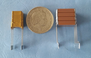
Figure 1: A BME 4-stack capacitor for space applications (left) and a 4-stack PME capacitor with equivalent capacitance values and voltage ratings (right).
Current state of BME ceramic availability
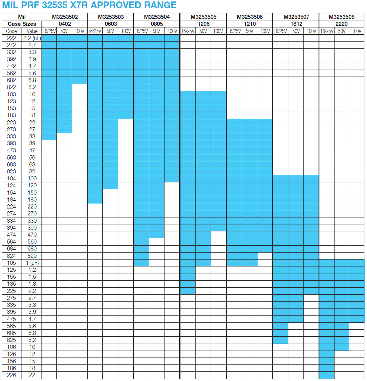
The European Space Agency (ESA), NASA S311-P838 and Mil Prf 32535 all have accepted BME products and specifications now exist for designers to utilize when creating flight electronics.
Depending upon the exact specification called, the AVX parts utilize a Sn/Pb plated Flexiterm® terminations, which provided enhanced resistance to mechanical stress by allowing for more board flexure than standard terminations. Case sizes range from 0402 to 2220 with capacitance values & voltage ratings extending from 2.2nF – 22uF & 16-100V.
The current state of Mil 32535 approvals is shown in the table below:
A future expansion of high reliability BME MLCCs will be the qualification of low inductance capacitors intended for decoupling advanced ICs. Low inductance BME MLCCs offer high capacitance in small packages and dramatically lower parasitic inductance. These components enhanced frequency response will allow a larger frequency spectrum of operation and will allow a smaller number of capacitors to decouple advanced ICs such as FGPAs. The combination of larger capacitance values in smaller capacitors and fewer capacitors needed per IC holds great promise in next generation flight system design.
How did BME get high reliability? Design
The capacitor design model used for high reliability BME “space “ capacitors employed a very conservative approach in which the individual dielectric layers, capacitor cover layers, and margin areas were selected to give the part additional protection from overvoltage stress and any external environment influences.
Figure 2 illustrates the typical construction of a high reliability MLC capacitor for space applications.
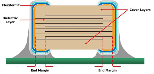
Figure 2: The typical construction of a high reliability BME MLC capacitor for space applications.
MLCC product design has four key component areas:
- Dielectric layer thickness
- Side/end margin dimensions
- Capacitor cover layer thickness
- Capacitance value
Ceramic Layer Dielectric Thickness
Commercial BME capacitors presently utilize fired dielectric thicknesses of anywhere from ≤2μm for low voltage (4V) X5R devices to ~80μm for the higher voltage (2kV) X7R devices. Typically, a 25–100 V X7R product would have a dielectric thickness in the range of 5μm to 18μm, depending on the actual voltage rating and the component supplier.
All of the AVX manufactured space products designed for the ESA evaluation utilize an extremely conservative approach that features an additional dielectric layer thickness beyond even the present automotive designs. For example, a 50V automotive grade capacitor would use a dielectric layer of around 4.5–5μm, but its equivalent space part is designed with a minimum ceramic layer thickness of 11μm (green/unfired dielectric) approximately 2 x greater giving enhanced product protection with respect to voltage stress and reliability performance.
Capacitor End and Side Margins
Capacitor margins protect the inner electrode structure from the outside environment, and the end terminations from opposing polarity voltages. These are usually made as small as possible in order to maximize the area of the electrode plates and, hence, the capacitance value. The minimum side and end green margins for a commercial part are around 75μm, and around 100μm for an automotive part. For the space designs, these margins are set at 170μm for 25V rated products to ensure an extra design safety.
Dielectric Cover Layers Top and Bottom
The cover layers that are set on the top and bottom of the internal electrode stack are normally a minimum of approximately 75μm for a commercial part and 100μm for an automotive part. The space designs feature a minimum cover layer thickness of 112μm for the 25V parts, 160μm for the 50V and 100V parts.
Bulkhead mounted EMI Filters – Emergence of Micro Miniature options
Bulkhead Filter Description
EMI control is of growing importance as systems shrink in size and electronic content grow in complexity and processing speed. Small, lightweight, high performance EMI filters are of great use to designers. A Bulkhead filter is a device that mounts into a hole that exists in the system box wall and passes signals from the outside environment through a variety of optional filter types to the internal box environment. See Figure 3.
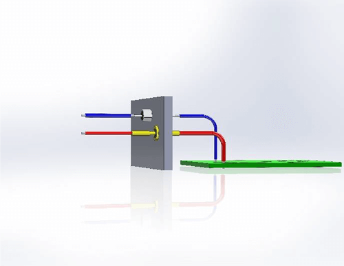
Fig. 3: Typical Bulkhead Filter Wall Mount use Cross Section
Bulkhead filters either can bolt or be soldered into the systems box wall. Additionally arrays of Bulkhead filters can be created that would allow a Bulkhead filter array to be soldered, conductive epoxied or brazed onto a case. Arrays of bulkhead filters are sometimes associated with pogo pins touching the filter pads (in the case of Power/battery charging).
Regardless of the exact form factor, internally the signals on each side of the filter are connected through the filter network. Common filter configurations that exist within the filter can be C, L, T, Pi, LC, CL and transient suppression in functionality.
Internal Construction of a Bulkhead Filter
Discoidal capacitors are used as the capacitive element in many bulkhead mounted EMI filters. See Figure 4 for a discoidal capacitor metallization and how it is used within a simple bulkhead filter.
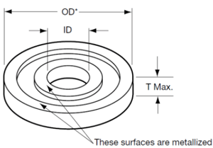

Figure 4: Discoidal Capacitor Metallization (left), Bulkhead Filter Cross Section (right)
Discoidal capacitors are a circular form factor device. Discoidal capacitors have an inner metalized hole/termination for one set of electrodes and the outside round edge of the capacitor is metallized to connect the opposing electrode set. The outside metallization is then either soldered or conductive epoxied into place within the plated metal housing of the bulkhead filter.
The ceramic dielectric of the discoidal capacitor can be based upon any dielectric however; this paper considers NPO/C0G and X7R dielectric based products.
The inductors used in bulkhead filters can range from ferrite beads to magnetic core and wire wound devices.
Once the internal design of the filter has been completed and the filter is electrically assembled, the internal components are then isolated from the outside environment using either epoxy resin (for nonhermetic parts) or a glass seal (for hermetic parts). A combination of epoxy/glass can be used if one end of the filter is needed to be hermetic.
The resin is selected by its compatibility to the internal components CTE as well as its ability to seal the internal filter from effects of external moisture in the use environment. Epoxy provides enhanced shock & vibration characteristics since it acts to cushion and hold the internal filter components in their original positions. Unlike resin-filled filters, hermetic devices have a glass to metal seal soldered onto the metal housing to provide zero possibility of outgassing and to provide the highest level of environmental isolation between internal filter components and the outside world. Regardless of the type of filter used – hermetic or resin filled – care must be taken to not adversely affect the filter by excessive torque or heat when installing. Excessive torque can deform the metal housing & impart stress to the ceramic thus causing cracks on the discoidal capacitor in the case of resin-filled filters. Excessive torque on hermetic case filters can break the devices hermetic seal and cause cracks in the ceramic discoidal capacitors as well.
When properly selected and installed, bulkhead filters provide high reliability operation and the highest attenuation filter responses. The use of bulkhead filters represents a best-case control method of EMI because attenuation occurs at the faraday cage (case or frame wall) rather than after the signals enter the case. Filtering within the case wall does nothing for controlling signals radiated off or conducted onto lines prior to the PCB based filter.
In addition, the parasitic content of the discoidal capacitors is greatly lower than that of discrete capacitors used on a PCB. Therefore the electrical response of filters is based upon nearly ideal capacitors – discoidal capacitors with low parasitic loss greatly eclipses filters based upon discrete passive components placed on a pcb in any of the filter types previously stated. Not only is the package inductance of the MLCC higher relative to the discoidal but the trace dimensions and SMT pads add considerable inductance. Those higher parasitic inductances and capacitances limit the frequency response of any filter based upon discrete passive devices. Depending upon the case size, discoidal capacitors can exhibit inductance 1/20 that of MLCCs.
Filtering size reductions
As in the case of Space qualified BME MLCCs, the needs for smaller lighter filters is easy to understand given that the cost of launching 1 pound of hardware is approximately $10,000. With this in mind, weight and volume reduction is key to future systems performance BUT these reductions cannot come at the expense of filter capability, throughput current rating or reliability.
Two simple methods exist to increase filter density on a box wall.
The most obvious is to use round head filters vs. those with hex head configurations. Round head filters need virtually zero clearance for assembly & torqueing relative to hex head filters. Round head filters can be tightened with modified tools on the vertical axis of the filter. Though this will not reduce overall volume or weight of filters – it would allow tighter packing on I/Os and a potentially end higher box density.
The next option is to consider custom filter plate assemblies that utilize round case filters fitted into custom steel, brass or aluminum plates designed for maximum density and minimum stress to the individual filter. Assemblies allow end users to receive finished high-density filters that have been torqued, soldered and tested prior to shipment.
A comparison between Hex head filters, round head filters and custom plate assembly is shown in Figure 5.
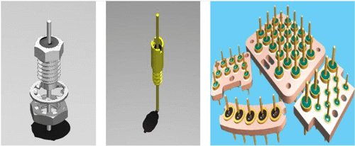
Figure 5: Hex Head (left), Round Head (center), Custom Plate Filter Assembly (right)
However, in order to achieve the true weight and volume reductions needed for nano and microsats – miniaturization of filters must be utilized. Miniature bulkhead filters are specially designed for a reduction in mass/volume over traditional filter types. The various miniature filter families are based upon the smallest discoidal capacitors available as well as size-reduced inductors. The miniaturization trends of bulkhead filters can be grouped into three families – miniature, sub-miniature and micro-miniature. A comparison of weight, hole diameter, type and range is shown in Figure 6.
Regardless of the specific family chosen, the volume and mass of miniature classes of filters is spectacular even when compared to discrete SMT capacitors. For example, a 0805 MLCC weight is approximately 0.020 grams and occupies 0.0049 cc. If PCB pads and ’keep out’ rules were added to the 0805 discrete capacitor example, the total volume used would nearly double (~ 0.0085cc) and the filter response would be possibly 10% as efficient as a bulkhead mounted filter. Note – the efficiency estimate depends upon a complex weighing of frequency response needs and routing impacts. This number is somewhat subjective and could vary greatly depending upon end designs.
These three classes of EMI filters (Miniature, Sub-miniature, Micro-miniature) offer all classes of satellite and launch vehicles measurable & significant weight & volume reductions that must be considered.
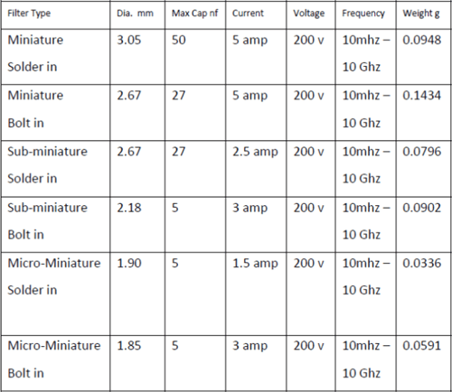
Figure 6: Comparison of Miniature, Sub-Miniature and Micro-Miniature Filters
Summary
BME electrode MLCCs offer designers high reliability performance and have been approved in three high reliability specifications. Data continues to be gathered that proves the BME material system is suited for high reliability applications. Further, new form factor BME MLCCs are planned to emerge for low inductance applications.
Advanced in ceramic capacitor technology have allowed discoidal capacitors to reduce their size dramatically. Smaller discoidal capacitors are the foundation of miniature, sub-miniature and microminiature EMI filters that offer designers similar performance in packages 95% smaller than traditional EMI filters.
Access to these critical components can be ensured early in the design phase by working with an authorized distributor and leveraging their relationship with the supplying manufacturer. This can improve the total efficiency and document the security of the supply chain.